
Digital Rectification

Overview
With digital rectification, images from any camera can be evaluated very quickly and easily in two dimensions or even to a limited extent in three dimensions. The transformation parameters are obtained with the help of a square of 5 lines or 4 or more spatially known points (control points). In principle, no orientation is required or calculated for the image to be rectified.
Definition of a Rectification Plane with 5 Distances
Procedure
- Activate the image to be rectified: Load it by double-clicking on it in the image overview of the project manager.
- Start the corresponding measurement dialogue: Plane over 5 distances
- Enter the known 5 distances of the quadrilateral . One of the 6 distances of the quadrilateral (incl. diagonals) must have the value 0.
Measure the corners 1-4 in the activated picture, they are arranged counter-clockwise. Point 1 will get the coordinates 0,0, point 2 determines the orientation of the X axis - Close the dialogue with OK. ELCOVISION 10 now asks if you want to transform the plane you have just defined into an existing coordinate system or not. If yes follow the instructions of ELCOVISION 10.
- If required, the plane can now be cut out (limited) at will. This can be done with the command Cut out plane.
You can repeat the plane measurements as often as you like. After the first 4 measurements the 1st point of the plane definition is measured again.
Planes can be clipped with a polygon. If you do not define a boundary for a plane, the rectification plane is valid for the whole photo.
Measurement dialogue "Define ELSP plane over distances
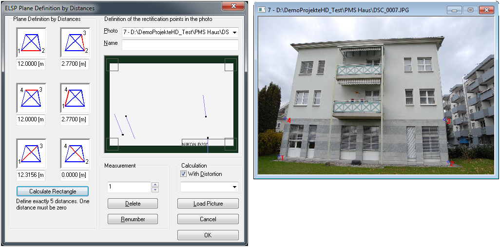
Plane Definition by Distances
Enter 5 of the known distances here. The coordinates of the end points of the vertexes are calculated by ELCOVISION 10 automatically by means of an arc cut. One distance must be 0.
Calculate Rectangle
If the rectification rectangle is approximately a rectangle it is sufficient to enter the first two distances of the plane definition and let ELCOVISION 10 calculate and enter the remaining distances..
Photo
Here you can select the photo for which you want to define a rectification plane. If you don't select an image, the one in which you make the first measurement will be selected automatically.
Name
You can assign any name or comment to the rectification plane.
Definition of the rectification points in the photo
Here you can see the currently measured points of the rectification plane
Measurement
Here you will be told which measurement in the photo must be taken next. After measuring the 4 points you start again at point 1.
Delete
You can delete a measurement as you wish. You can also repeat a measurement with the same point number. ELCOVISION 10 will ask you what it should do with the measurement..
Renumber
You can assign a measurement to another point using this button
Calculate - With distortion
If this option is selected, the camera distortion is taken into account. This can lead to drastic increases in accuracy.
Load Picture
Once you have selected an image from the list, you can simply use this to reload the image.
Definition of a rectification plane using 4 or more points
Requirements
- You need to have at least 4 3D points present. If an ELCOVISION 10 .coo or Leica GSI file is available load it into ELCOVISION 10.
- If you are working in an ELCOVISION 10 CAD plugin you can click on object points directly in your drawing during the measurement. These points are then transferred into the project.
If the images are oriented, the points required for the planes can be shown or hidden in the images to make it easier to select them.
ELCOVISION 10 uses automatically existing measurements of orientation points for the definition of rectification planes.
If you use oriented images for the definition of the rectification planes ELCOVISION 10 calculates the corresponding measurements by a spatial backward cut and suggests them to the user. The user can simply accept them.
Procedure
- Activate the image to be rectified: load it by double-clicking on it in the image overview of the project manager.
- Start the measurement dialogue
- Select at least 4 points in the point list, or click at least 4 points in the point display, or enter the point numbers of the points directly. If the points are in a CAD, you can also click on points in a view window of the CAD, these points are then automatically transferred to the point list. If you use more than the necessary 4 points to define the plane ELCOVISION 10 creates a balanced plane by the selected points. The rectification parameters are determined by a balanced projective transformation
- Measure the points in the activated image the points. Pay attention to the point number because this is the logical assignment of the measurements with the object points.
- ELCOVISION 10 calculates during the measurement a balanced rectification plane through the measurements and displays the result and the deviations continuously.
- Close the measurement dialog with OK
- If required, the plane can now be cut out at will. This can be done by cutting out or limiting rectification planes.
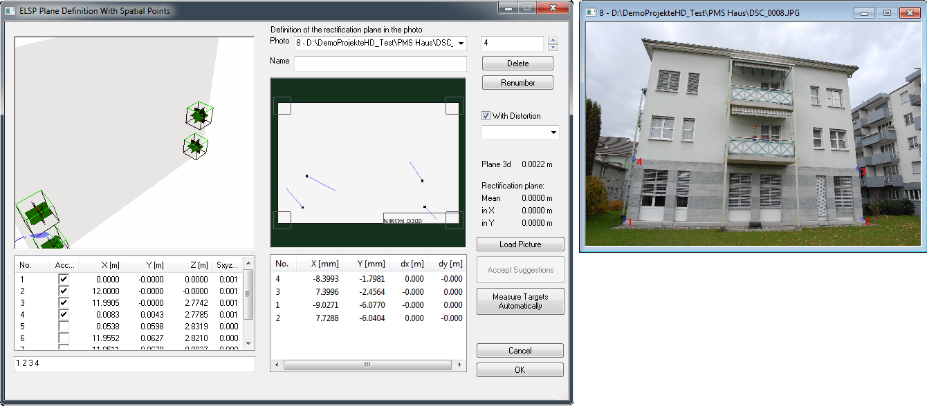
Measurement dialogue "Define ELSP plane via points"
You can activate points in a variety of ways:
- Click on the point in the point cloud
- Select the item from the item list
- Enter the point number of the point in the input line.
Point cloud view
In the point cloud view all object points and camera positions are visible. The balanced plane through the selected points is displayed as a semi-transparent rectangular plane. Use the point cloud view also to check if the selected points are really in one plane.
Point list
In the column Deviation the distance of the point from the balanced plane is shown: Distance of the point from the perpendicular base of this point on the balanced plane.
Photo
Here you can select the photo for which you want to define a rectification layer. If you don't select an image, the one in which you make the first measurement will be selected automatically.
Name
You can assign any name or comment to the rectification plane.
Measurement overview as graphical view
Here you can see the points of the plane that have just been measured. The deviation vectors to the measurements are also shown.
Measurement overview as list
Here you can also see the points of the plane that have just been measured. In the column dx and dy you see the deviations at the measured point listed in object units.
Delete
You can delete a measurement as you wish. You can also repeat a measurement with the same point number. ELCOVISION will ask you what to do with the new measurement. You can keep the old measurement, replace it with the new one or let ELCOVISION average the measurements..
Renumbering
You can assign a measurement to another point using this button
Calculation - With distortion
If this option is selected, the camera distortion is taken into account. This can lead to drastic increases in accuracy.
Point Deviation
Here you see the average deviation over all points and the deviation broken down into X and Y. The unit is in object units.
Load image
Once you have selected an image from the list, you can simply use this to load the image.
Accept the measurement suggestions
If orientated images are used ELCOVISION 10 calculates the corresponding image measurements by means of a spatial backward cut.
These are shown as a red double circle in the images. It is enough to simply click on this circle and the corresponding measurement is taken over.
If several measurement proposals have been calculated, all of them can be accepted at once with this button.
Measure targets automatically
Any target marks are measured automatically and existing object points are automatically selected to define the rectification plane.
Definition of Rectification Planes using Oriented Images and Spatial Planes
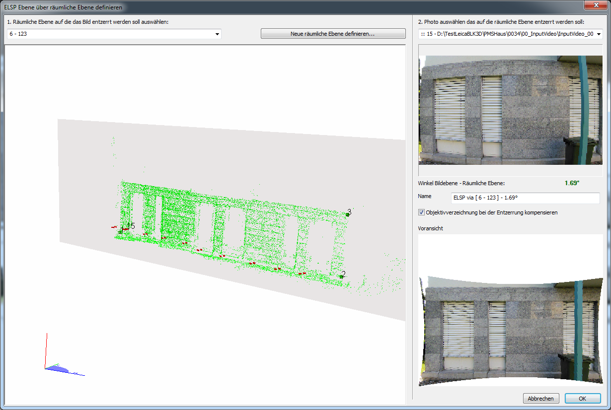
Overview
This makes it very easy to define rectification planes in images without having to measure points.
This function can be used optimally in this way:
- Automatic orientation of the images and eventually calculate a high density point cloud.
- Select the part of the point cloud that lies on the desired rectification plane: Then right click > Spatial plane through selected points
- With the help of the above dialogue find images which look as perpendicular as possible to this plane and let define the rectification planes there.
Requirements
- Oriented images
- Spatial planes that can be defined or constructed using points
Cutting rectification planes
Overview
Here, rectification planes can be duplicated and cut out as desired. For example, a window layer can be defined for an entire house front, in order to then clone (copy) a layer for each individual window and cut out the corresponding window.
Existing boundaries and layers can be duplicated and deleted as desired. If a layer is duplicated, any existing boundaries are also copied.
The borders of a rectification layer can be edited at any time.
Procedure
- Activate the image to be rectified: load it by double-clicking on it in the image overview of the project manager.
- Start the measurement dialogue for the plane boundary.
- Select the layers to be delimited or click directly in an image on a point of the desired layer.
- Measure the corresponding boundary. If necessary duplicate the corresponding layers.
- When you have completed a border, click [OK] to close the measurement dialog box, or simply start measuring in a new image or plane.
Measurement Dialogue "ELSP: Form the Boundery of Planes"
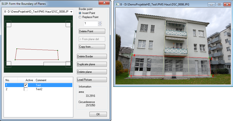
Photo selection
Lists all images in which a rectification plane has been defined. Select the desired image.
Measurement overview
Shows how the planes have been defined and how they are bordered. The currently active rectification planes are highlighted in red, the not active rectification planes are indicated by grey lines.
The current boundary point is highlighted by a small red square.
Plane list
Shows all rectification planes of the currently active photo. Here you can activate or deactivate a single rectification plane, you can also give the plane a new name or comment.
Border point
You have two options for adding border points to an rectification plane:
- Insert Point
The measurement is inserted as a border point between the current and the next border point. - Replace Point
The measurement replaces the current border point.
Point number
Here you can select the current border point. It is highlighted in the measurement overview by a small red square, in the measurement image itself a small red circle is drawn around the point
Delete point
This button deletes the current border point.
From plane definition
A boundary polygon is created for the currently active layer from its vertexes. A simple, closed path is determined.
Copy from ...
Copys a Plane Bondery from another plane
Duplicate Plane
Duplicates the currently active plane. The borders of the rectification plane are also copied.
Delete Border
Existing plane boundaries, which were taken over during duplication, can be deleted here if necessary. The border of the currently active plane is deleted..
Delete Plane
Deletes the currently active plane.
Load Picture
Once you have selected an image from the list, you can simply use this to reload the image.
Management of Rectification Planes
Properties Dialog
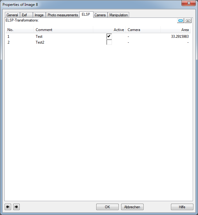
The properties dialog appears also if you measure in the overlap area of two rectification planes and ELCOVISION 10 cannot decide which rectification plane the measurement should be assigned to.
Then select the appropriate plane. Using the list you can also activate, deactivate and delete rectification planes of a project.
Activating and deactivating planes is especially valuable if you are measuring in the overlapping area of two planes.
By pressing the small button in the upper right corner you can determine a rectification plane without projection parameters. If you rectify such a plane, you will get a réseau corrected digital image.
Show/hide ELSP planes
With these buttons in the Ribbon Command Bar, active ELSP planes can be shown or hidden in the activated images.
If the "Rectification" measurement mode is activated, all active rectification planes are automatically faded in or out in the images.
Digital Rectification
Overview
ELCOVISION 10 is able to rectify any number of linked planes in digital images into an orthophoto. For this purpose the rectification planes must be nearly parallel. If the planes are not parallel to each other the non parallel planes are automatically folded into the view plane and a kind of unfolding is created.
The resulting image can be saved in any format or printed out to scale.
In a rectified image you can measure at any time during a point measurement, all 3D information of the original planes is preserved.
If a rectified image is saved in a TIFF format, a GeoTIFF file is automatically written. Other programs that can read this format will then receive the scale information for this image directly.
Procedure Digital Rectification
- Define the corresponding planes in digital images, link them and border the planes on the areas to be rectified.
- Start the dialogue Digital Rectification.
- Select the photos and planes which should be rectified to an orthophoto.
- Arrange the planes one after the other in such a way that the desired result is achieved. Check the result in the preview.
- Click OK to close the Digital Rectification dialog box and the rectified image is calculated. After some time it appears on the screen, you can now move around and measure directly in it. In the right-click menu of the image, you can obtain information on the rectification values, such as the pixel scale, etc.
- Save the rectified image in any format or print it out.
Dialog Digital Rectification
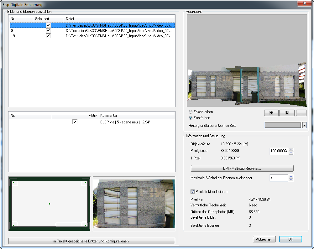
Select images and planes
Select the photos and rectification planes you want to digitally rectify. You can select as many planes as you like for each image. By activating the button "Selected" images are added, by activating the button "Active" planes are added..
Selected planes
In a small overview graphic you can see how these planes are defined and how they are bordered. Active planes are highlighted in red, non-active planes are shown in grey.
Rectification configurations saved in the project
ELCOVISION saves all orthophotos created so far in the project file. By pressing this button you can select the configuration of an orthophoto from a list of all previous rectifications and repeat this rectification. Of course you can also change this suggested rectification configuration.
Preview
Here you will find a preview in either real or fake colours. The depth of the rectified images can be changed with the arrow keys
A rectified image can have any background colour.
Object size
The size of the rectified image in object units.
Pixel size
The size of the rectified image of the rectified image in pixels. ELCOVISION 10 always selects those image sizes in which all details of the original image are still visible in the rectified image.
1 Pixel
Specifies the size of a pixel in object units. This information is useful if you want to transfer the image into a program that does not understand the GeoTIFF format. It is easy to transfer the scale information with it.
The pixel size and thus the size of the rectified image in pixels can be easily adjusted using the spin buttons.
Max Angle
Only those planes that are parallel to each other can be rectified into an orthophoto. Here you can set the maximum tilt angle that the planes may have to each other to be equalised together. Not parallel planes are automatically folded into the view plane, and thus a kind of unfolding is created.
Image size
This sets the image size in %. Basis is the resolution ELCOVISION has determined as the best resolution.
Reduce pixel effect
If images are rectified normally, "pixelated" images are created, edges and transitions become "stair-like". These effects can be suppressed by ELCOVISION 10 by a special procedure where details are not blurred. However the computing time for an equalization increases noticeably.
Pixel/[s]
Here you can see the calculation speed ELCOVISION 10 will use to equalise the image. This depends strongly on the type of the original images.
Presumable calculation time
Here the presumably necessary computing time, which will be needed to produce the orthophoto, is indicated.
Size of the orthophoto
This indicates how much memory the image will require.