
Getting Started Guide for Leica BLK3D
Here the configuration of the Leica BLK3D, import of a Leica BLK3D project, fully automatic orientation, generation of a high-density point cloud, a volume calculation and evaluation in a CAD are shown.
Requirements
- The Leica BLK3D has to be at least software version 2.08.1569. When you connect the Leica BLK3D to the internet it will automatically update to the latest version.
- Your computer must run Windows 10 or later otherwise you cannot connect the Leica BLK3D to the PC and copy the Leica BLK3D project files from the Leica BLK3D to your computer.
- ELCOVISION 10 must be version 9.040 or later.
Image Group Capture Mode
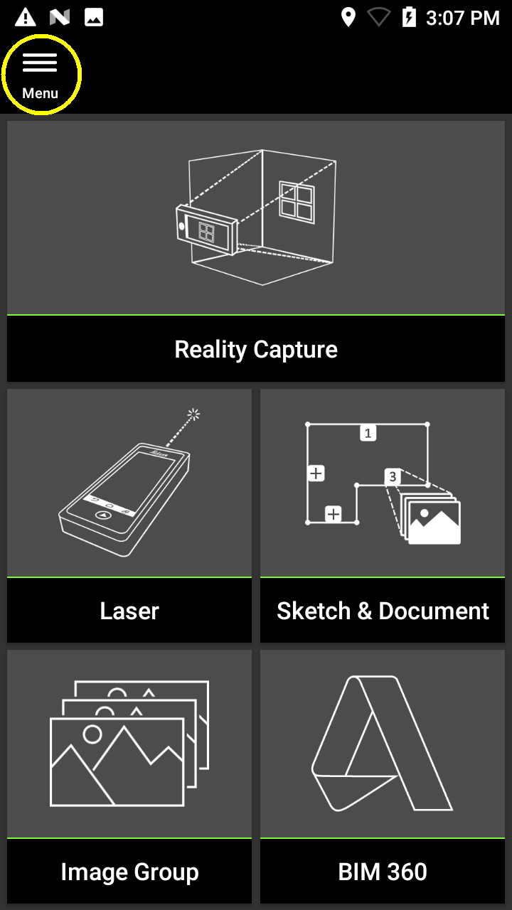
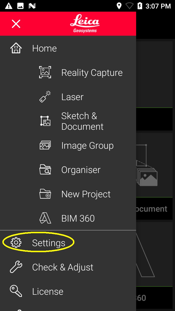
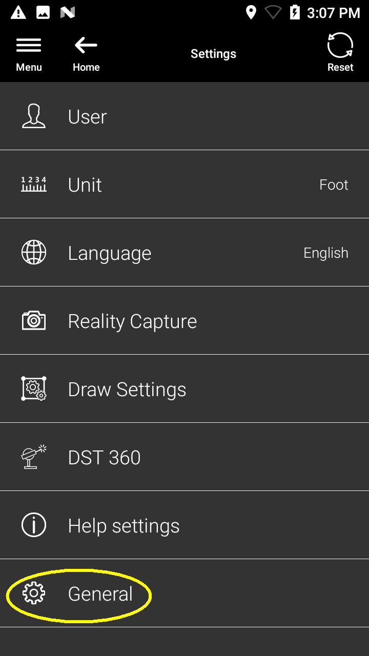
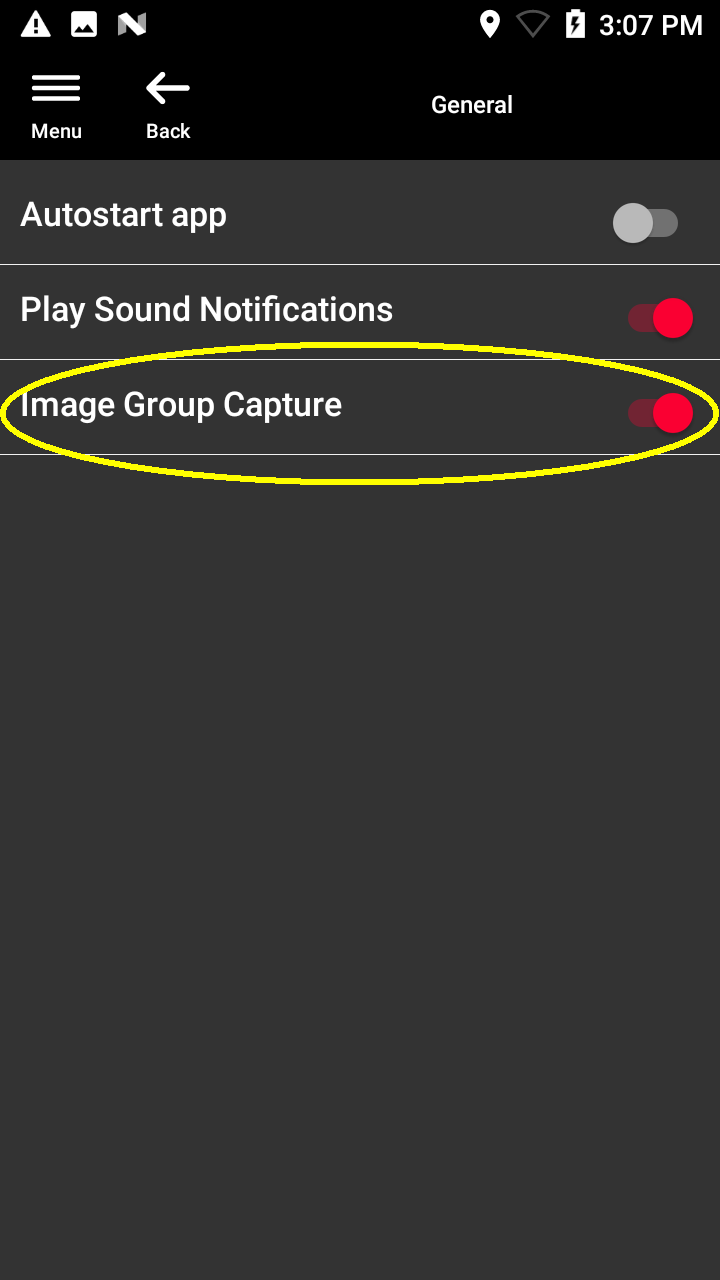
If this mode is active the Leica BLK3D can be used like a normal camera and any number of pictures can be taken.
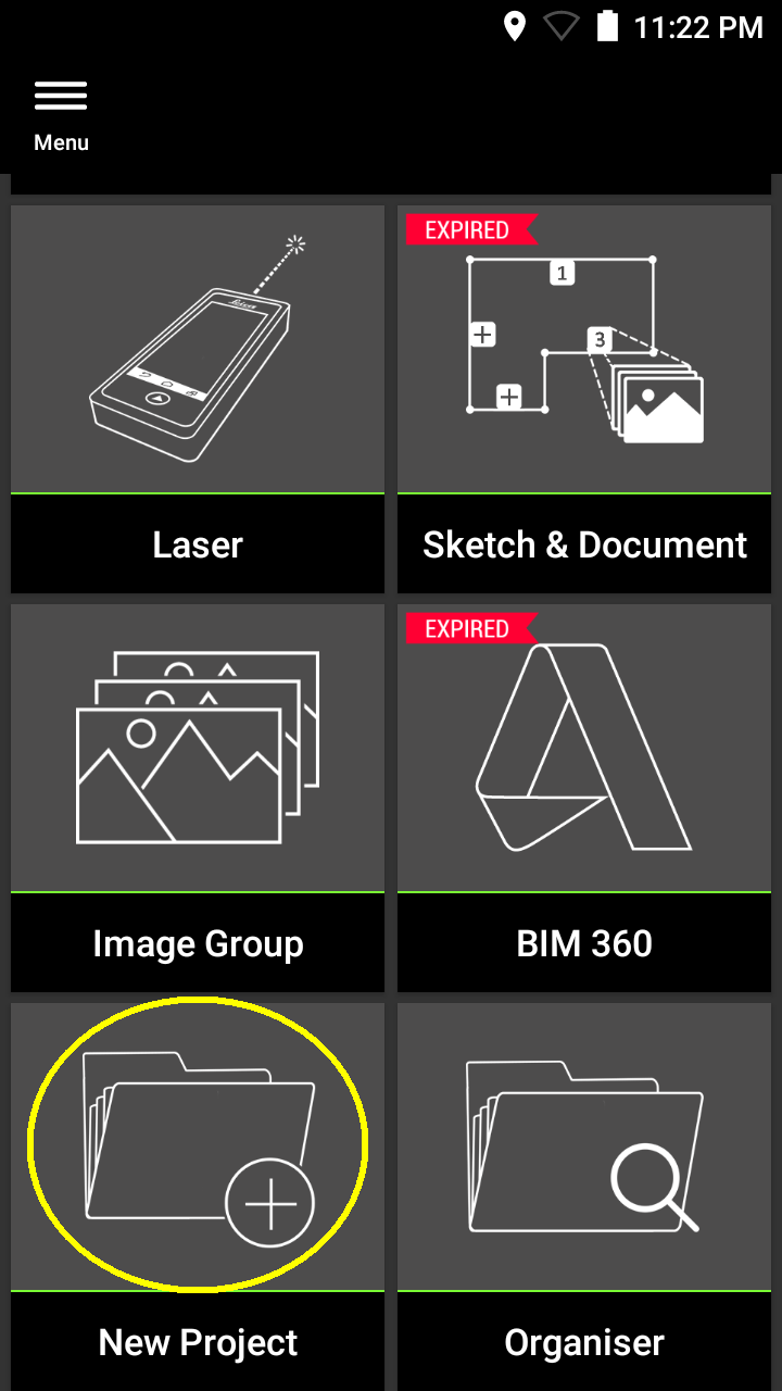
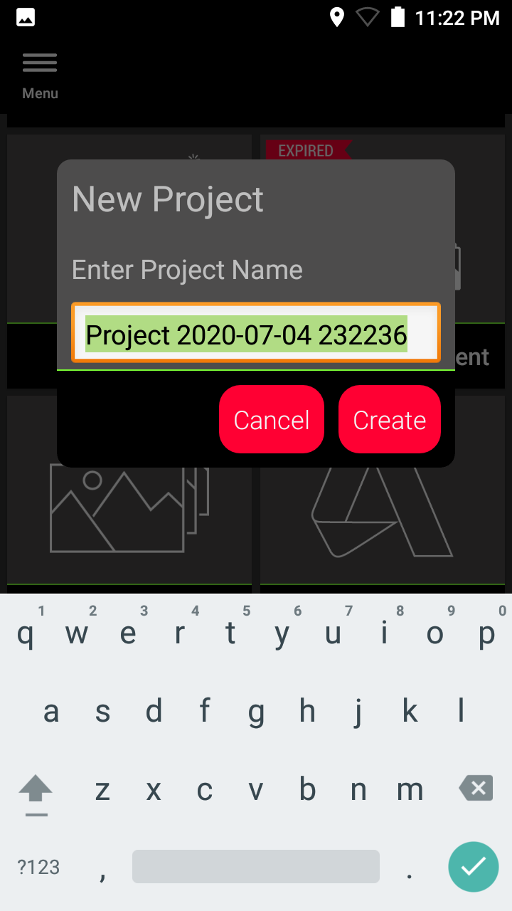
New project
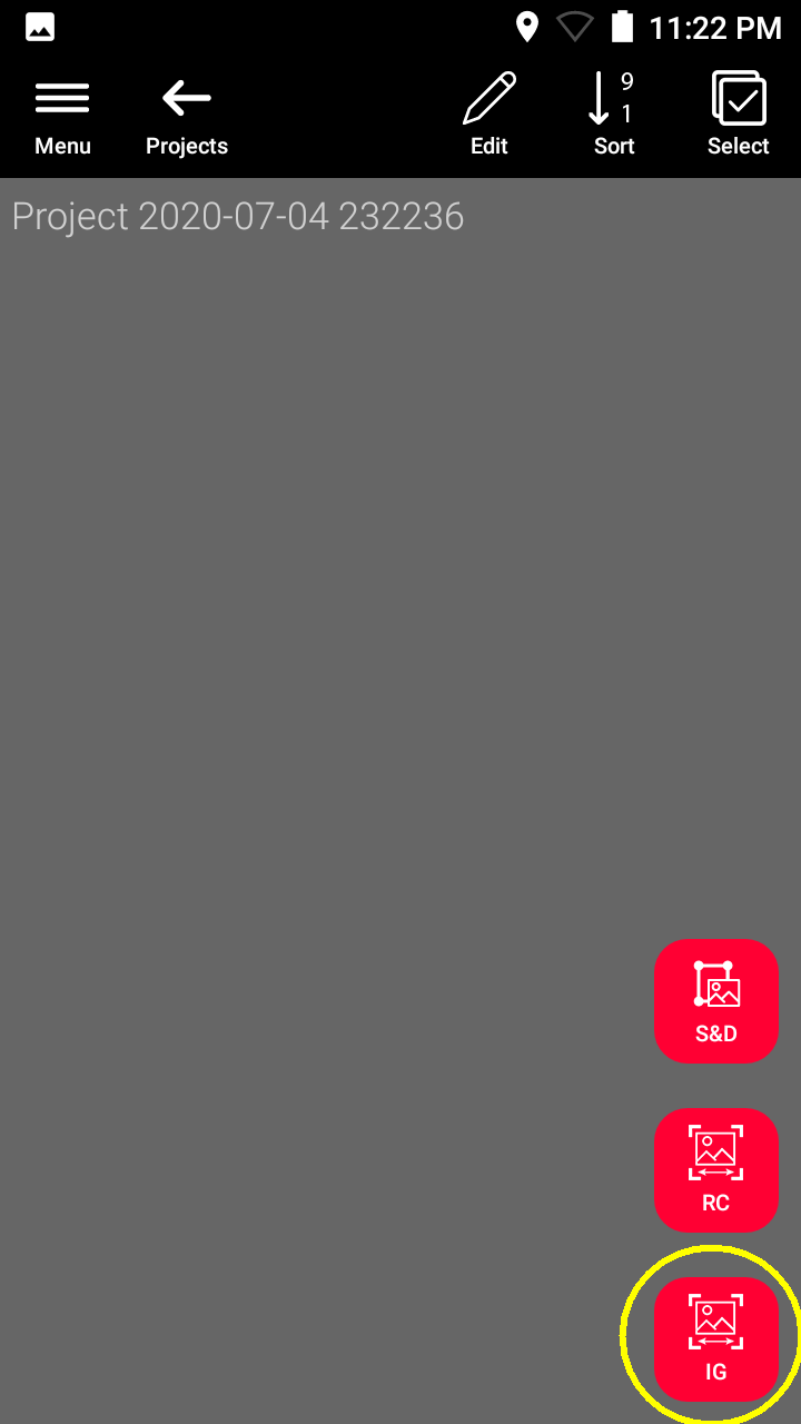
Then a new project must be created in "Image Group" mode:
Copy the Leica BLK3D project 1:1 to the PC
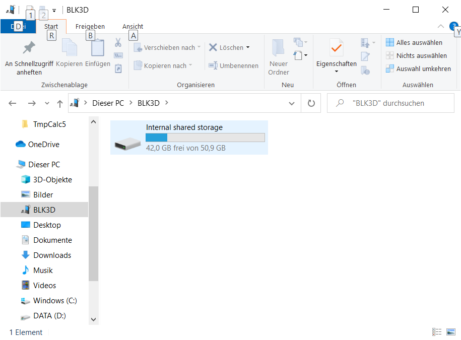
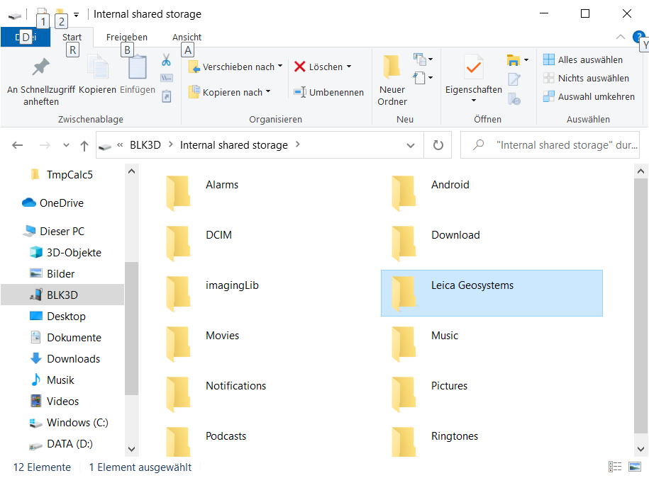


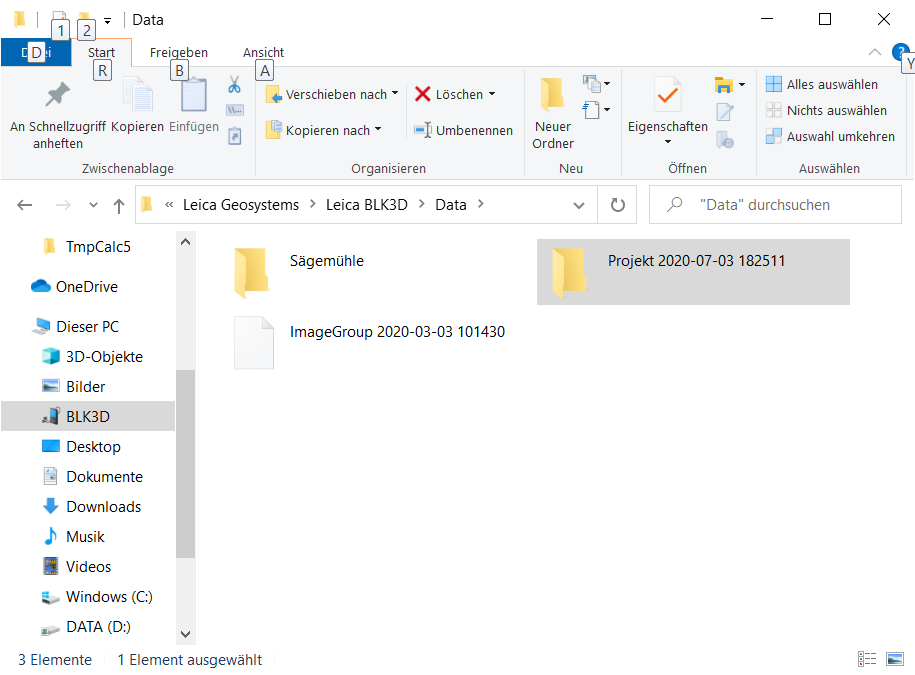
Do not change any paths or rename any files or folders!
Computation of the Point Cloud
Automatic orientation and generation of a high density point cloud
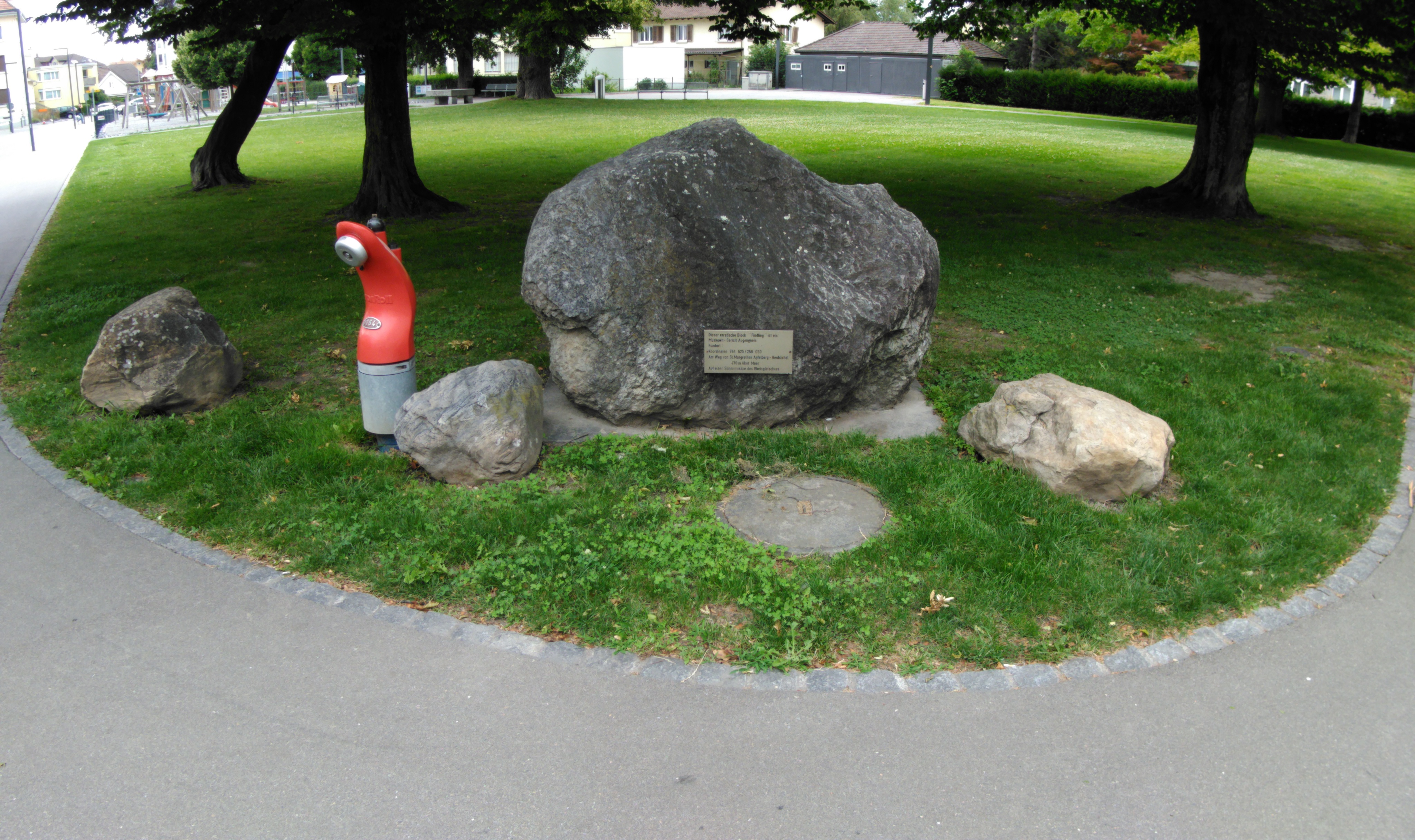
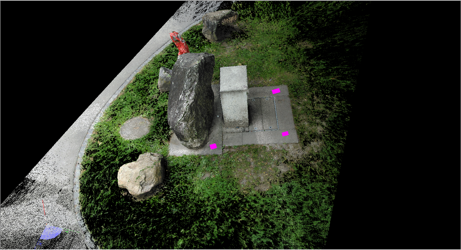
For this tutorial we use a set of images of an erratic block which we want to evaluate in different ways:
Here you find the Leica BLK3D project. Download it and unzip it to a local hard disk with at least 10 GB free space.
https://www.elcovision.com/ExamplesHD/Findling_CMI.zip
Start ELCOVISION 10 and open the Leica BLK3D project "Findling.cmi". The Leica BLK3D project will be loaded and interpreted automatically:
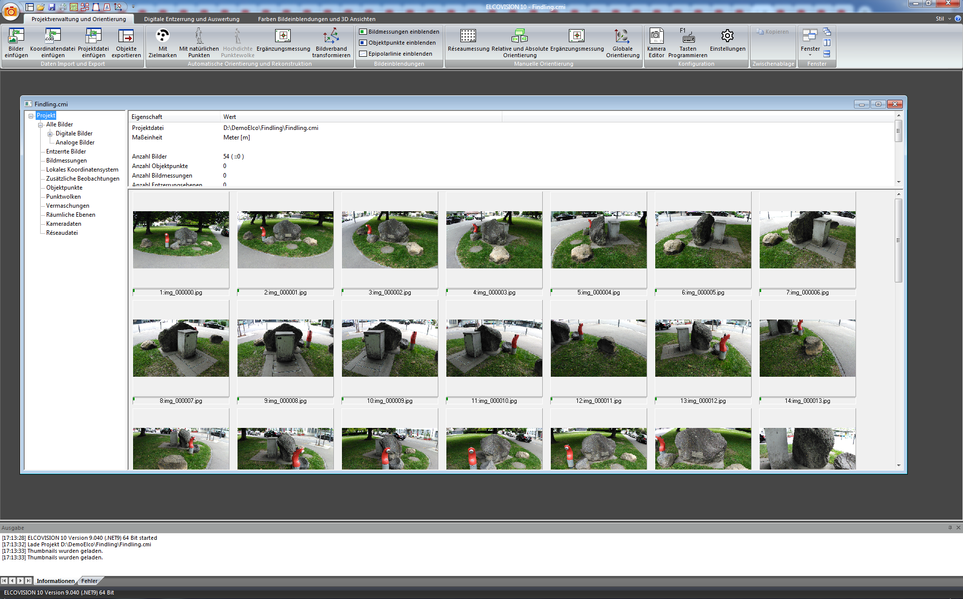
If the project window does not appear during loading, it is hidden somewhere in the background. At the top of the [Ribbon > Project Management and Orientation > Windows] select either Cascade Windows or Tile Windows.
Start the automatic orientation with natural points:
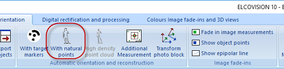
The following wizard starts:
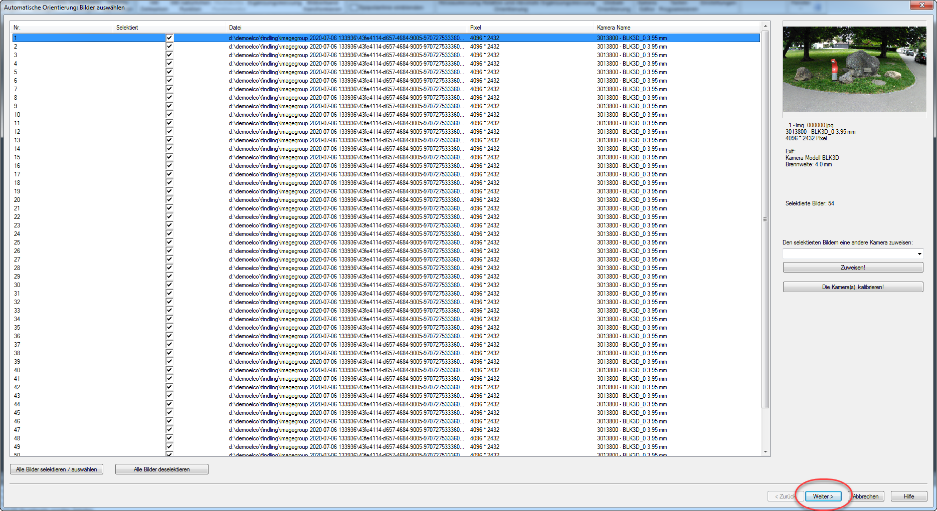
You see an information about the pictures, especially the information that a picture is 4096*2432 pixels in size is of immediate importance. Click Next >, the following page appears:
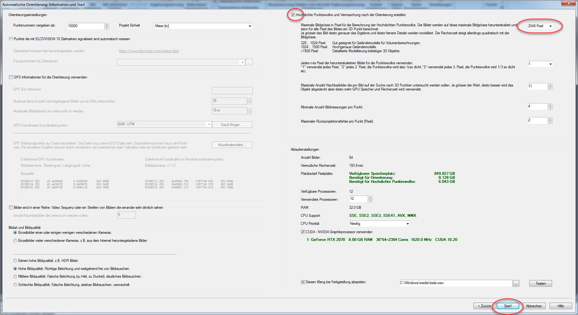
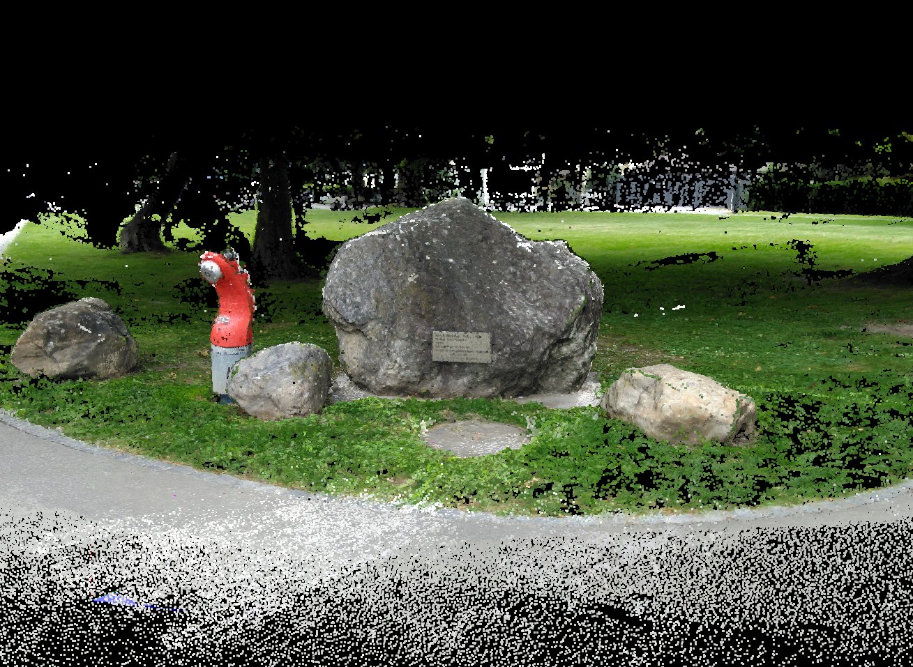
Check High Density Point Cloud and select 2048 pixels, i.e. half the image size, as the scale. This is a good compromise between level of detail and computing time. Click on Start!. After a few minutes you will get the following result:
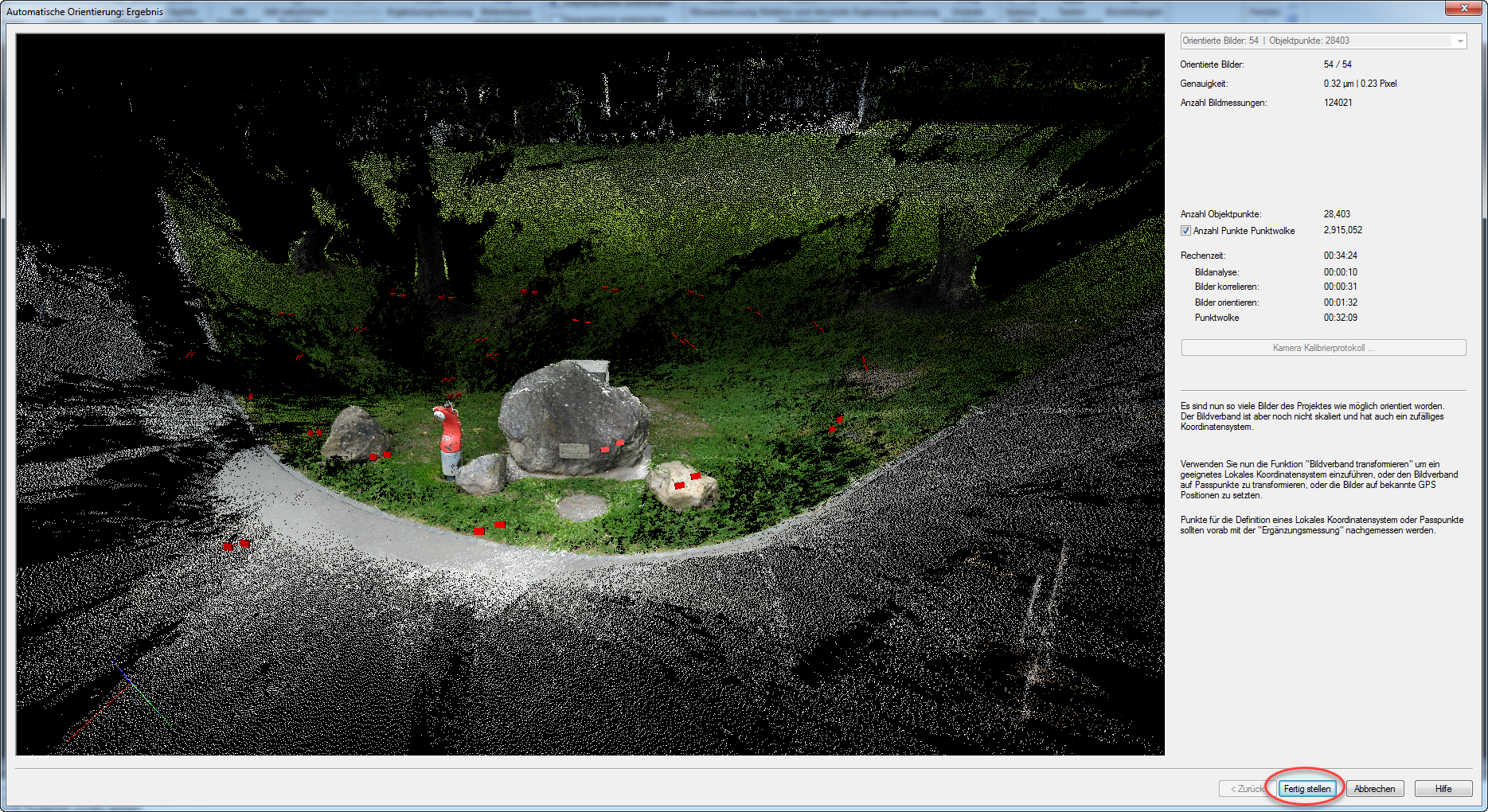
About 2.9 million points should have been calculated. Click on Finish.
The project is automatically scaled correctly by using the Leica BLK3D with its stereo cameras and automatically aligned correctly using its tilt sensors. We can immediately carry out any desired evaluation.
Trimming the point cloud
- Click on "Point Clouds" in the project manager
- Right click in the point cloud > "Point cloud true colors"
- By pressing the left mouse button you can rotate the point cloud, with the mouse wheel you can zoom into and out of the point cloud
- Rotate the point cloud so that you can view it from above.
- By pressing Shift and the left mouse button simultaneously, the point cloud view changes to selection mode. Drag a rectangle around the set of stones
- By releasing the Shift and left mouse button, the points within the selection rectangle are selected.
- Right-click > Crop selection
Evaluations
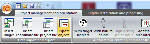
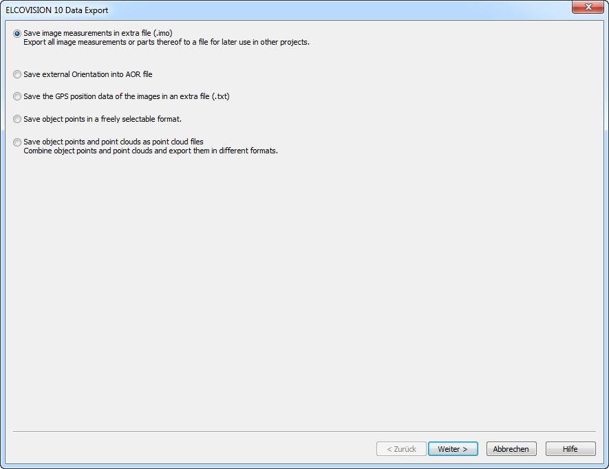
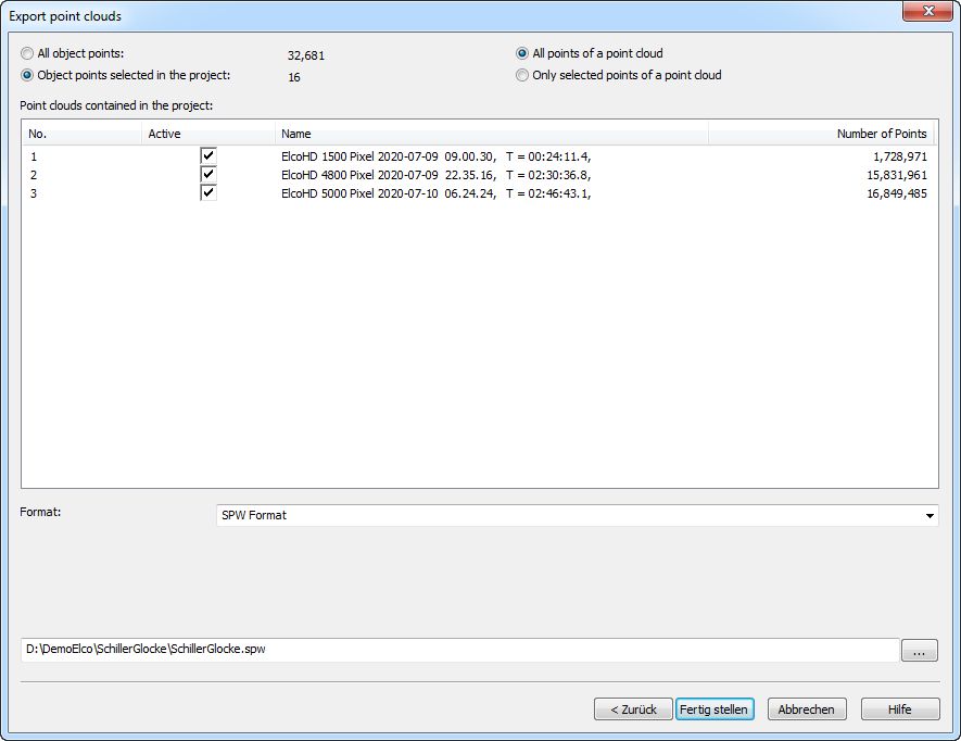
Export of the point cloud in various formats
The point clouds can be exported in different formats, either all points or only parts of them can be exported.
Volume calculation
The following is needed for a volume calculation: A reference plane and a mesh of the point cloud.
Definition of the reference plane
Select points in the point cloud, in this example the points on the concrete slabs are recommended:
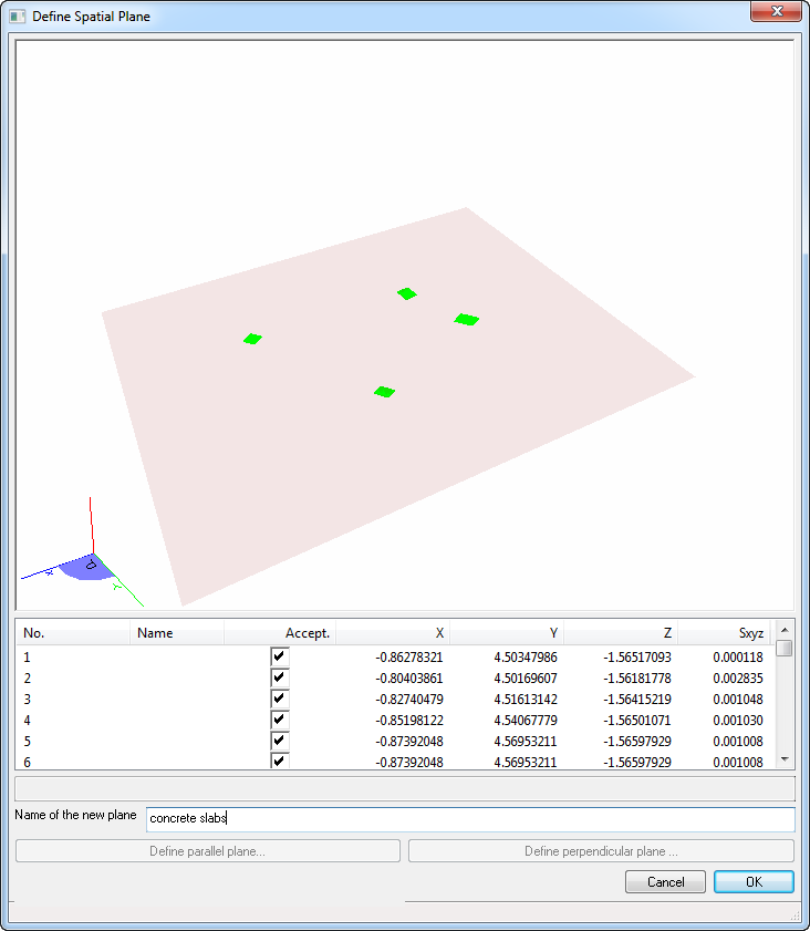
- Select well distributed points
- 3D View > Context Menu > Create spatial Plane from Selection or press R.
- Check the plane and give it a reasonable name and confirm with OK.

Meshing the point cloud
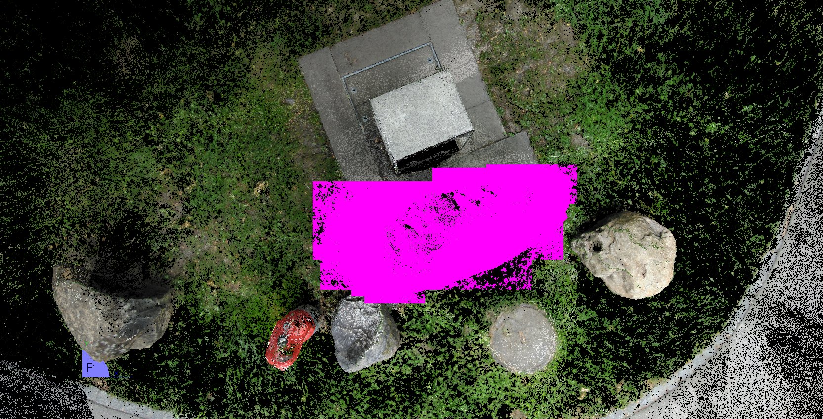
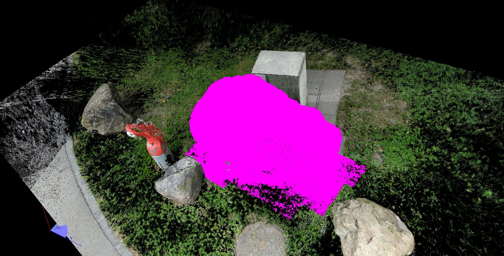
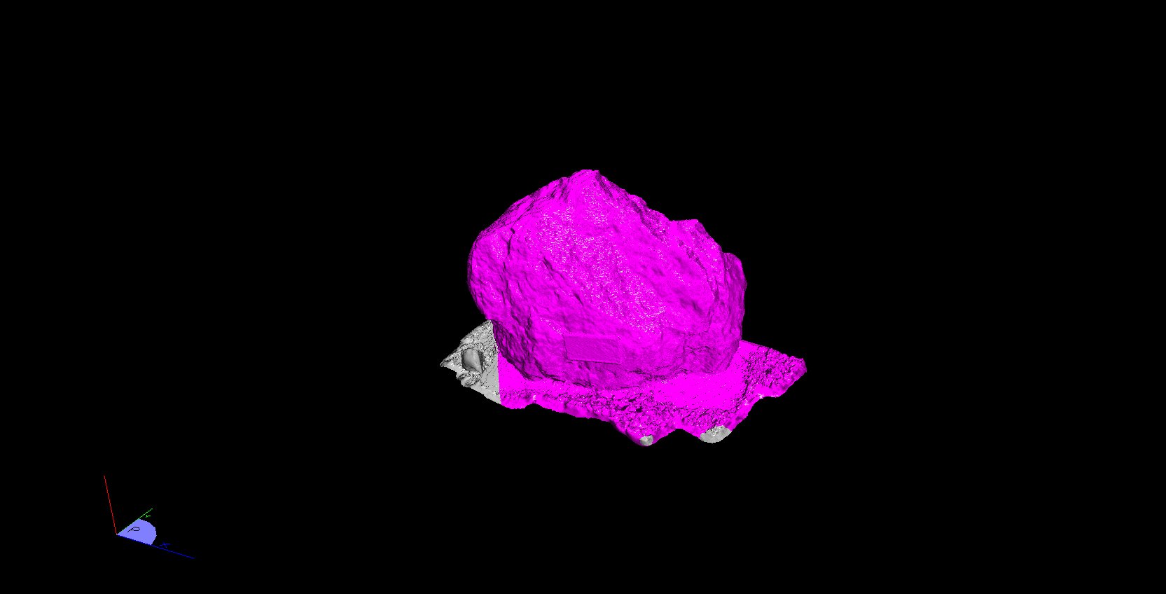
Select the boulder, it is best to choose a view from above:
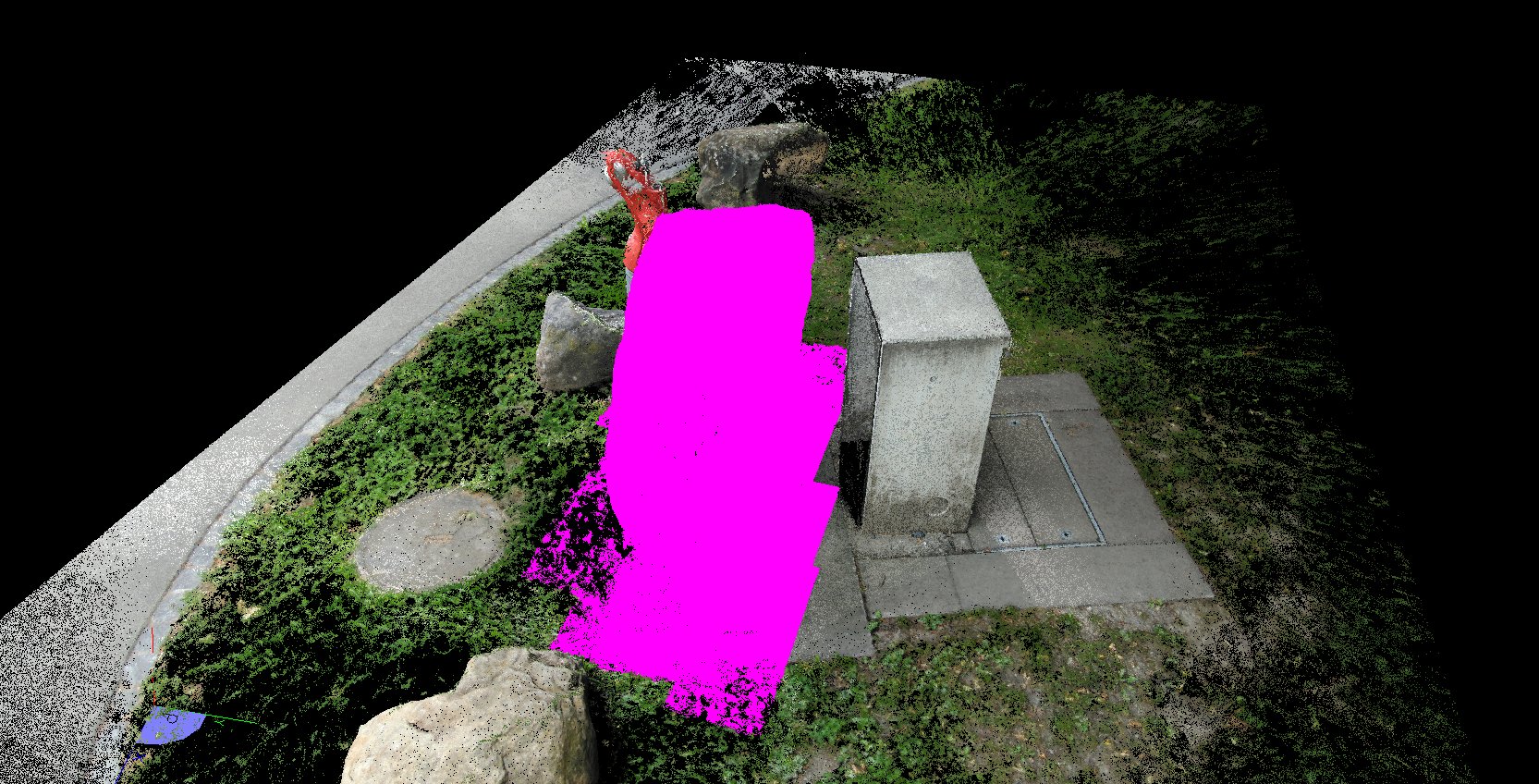
Calculation of the mesh
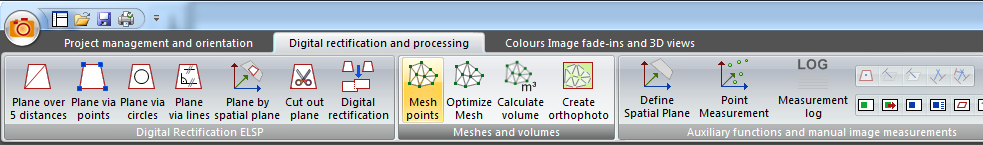
Choose Point Clouds and Object Points
Select the point cloud(s) to be meshed, you can see that only the selected part of the point cloud will be meshed. The Object Points interfere here and are deselected:
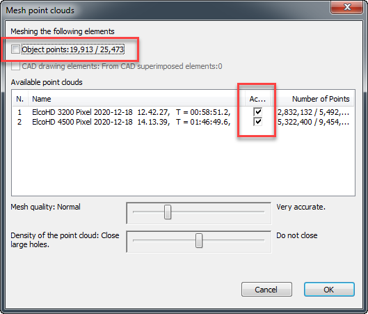
Press OK to close the dialogue and after a short time the mesh is calculated and displayed in the project manager under "Meshes":
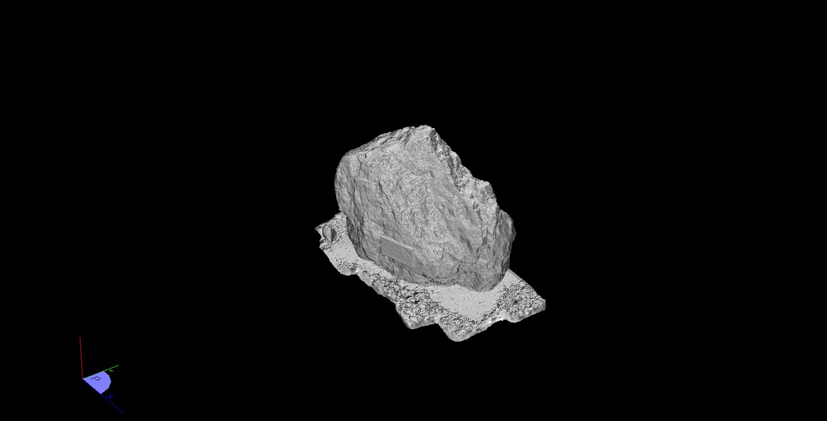
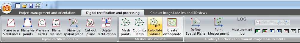
Calculation of the volume
If the mesh covers several objects or is larger than the volume you want to calculate, you can select the parts of the mesh that interest you:
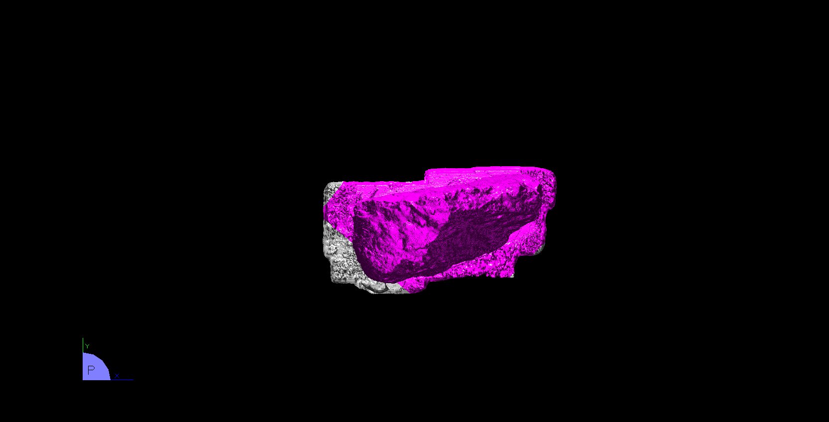

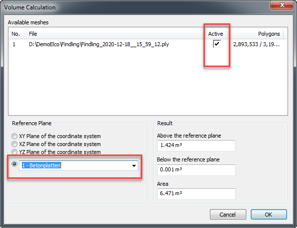
Make the calculation
The real volume of convex bodies like this boulder is calculated. In addition, the area of all meshing triangles is added up and output as the area of the solid:
CAD evaluations
- Save the ELCOVISION 10 project and close ELCOVISION 10.
Start BricsCAD. At least version 20.02.07 is required - Start the ELCOVSION 10 plugin by typing "elcovision" or "elcovisiondemo" in the command line of BricsCAD
- Open the ELCOVISION 10 project (.proX) with the Open Project command in the ribbon bar and position the drawing window and the project window side by side.
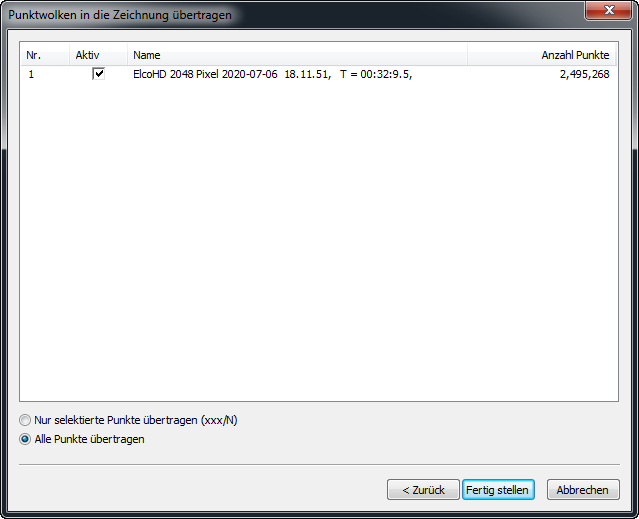
Import the point cloud into a BricsCAD drawing
- Save the drawing. This is necessary because the point cloud is referenced into the drawing.
- Start the point cloud export.
- After a short time the point cloud is imported into the drawing.


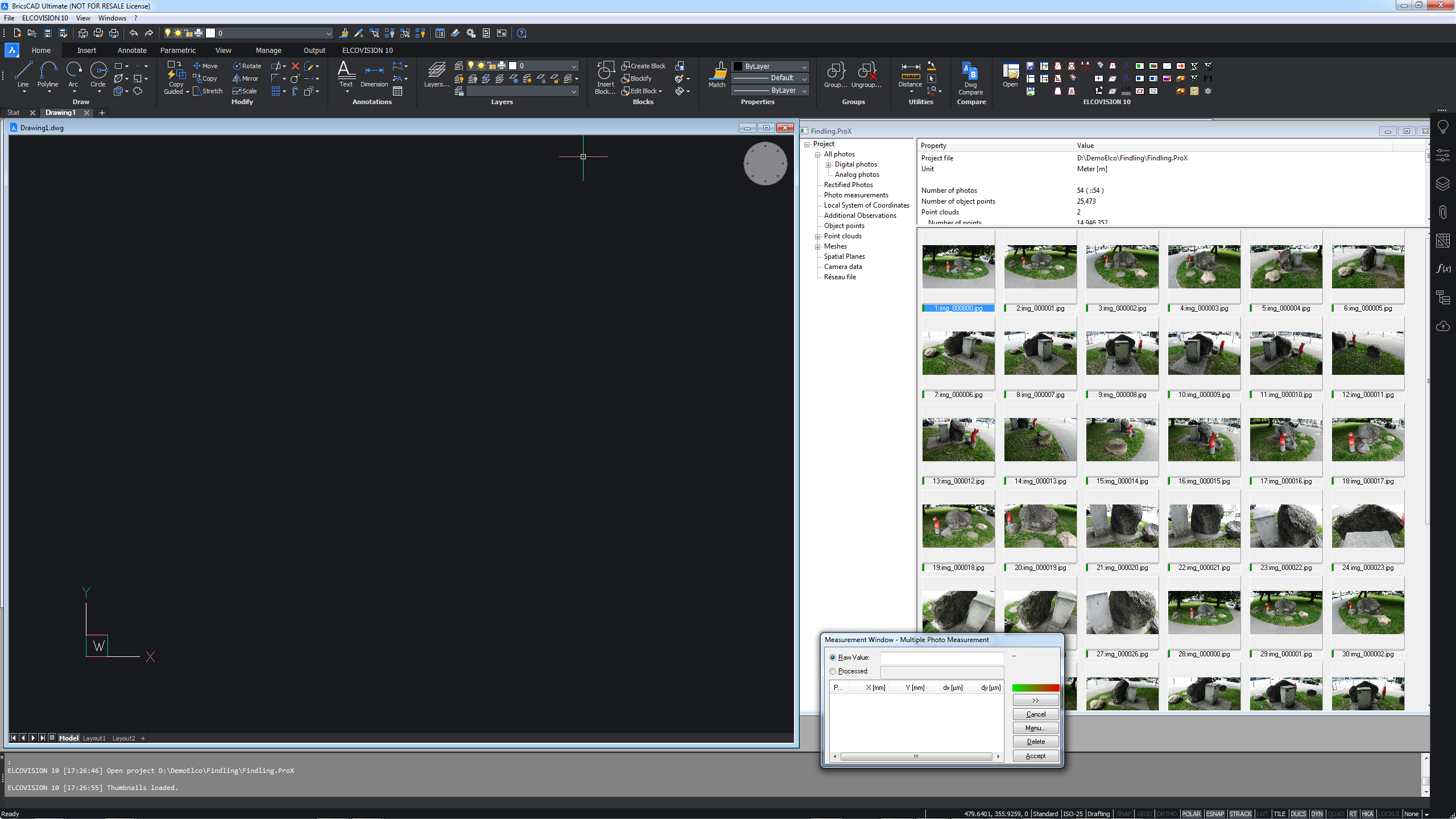
Drawing using image measurements
- Load the images in which you want to measure by double-clicking on the overview images in the project manager.
- Arrange the drawing window and the images sensibly on the monitor.
- Start the desired drawing command, here we use "line" as an example.
- If necessary, switch to one of the desired measuring modes, here we use the two-image measurement: The measuring mode can be switched at any time in the ribbon or in the Measurement Window - [Menu...].
- Measure the first point in both images, the result is automatically transferred to the CAD command line. The line command starts the line at this point.
- Measure the second point in both images, the result is automatically transmitted to the CAD command line. The line is now 1 segment long.
- The line can be extended with any number of measurements.
Video
Things to know
- Almost every drawing command of the CAD can be fed with the results of image measurements.
- The measurement mode can be changed for each point: For example, the first point can be created by a multi-image measurement, the second with a single-image measurement, the third with a two-image measurement, etc.
- The ELCOVISION 10 tools have numerous additional drawing commands that are optimised for surveying tasks.
Superimposing a Drawing into the Images
For documentation purposes or for further analysis, a drawing can be superimposed into oriented images.
- Start the command Superimpose Drawing into Images
- Start the select command in the dialogue that appears
- Select the drawing elements in the drawing that are to be superimposed.
- Press Enter in the command line to return to the dialogue.
- The selected drawing elements are now superimposed in the images.
Video