
Manual Image Measurement Methods
Rectification
Measurement principle
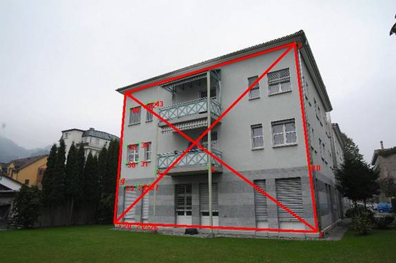
A flat rectification plane is defined in an image. This plane describes the transformation of the image coordinates into a local coordinate system of the rectification plane. During the rectification measurement, 2D coordinates are actually measured.
By spatially positioning the rectification plane, e.g. by defining it using Object Points, coordinates are obtained in the object coordinate system, i.e. 3D coordinates.
Requirements
- Image from any camera
- At least one defined rectification plane in the image used.
Achievable accuracy
Very high - High - Medium - Low
Automatic detection of measurement errors
Not possible
Potential sources of measurement errors
- Bad photo capture configurations.
- The rectification plane does not correspond to the intended evaluation plane.
Single-Image or Mono Image Measurement
Measurement principle
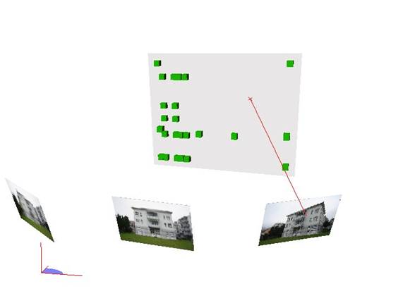
The measuring ray of an image measurement is intersected with a 3D plane. This plane is defined in advance using at least 3 points. If a more than 3 point are used to define the plane, a balanced plane is computed.
The coordinates of the piercing point of the measuring ray through the 3D plane are evaluated as 3D point coordinates.
Requirements
- Oriented images of a metric camera or simultaneous calibrated images of any camera
- A 3D plane
Achievable accuracy
Very high - High - Medium - Low
Automatic detection of measurement errors
Not possible
Potential sources of measurement errors
- The measurement plane does not correspond to the desired evaluation plane: e.g. with a slightly curved facade
Two-image measurement
Measurement principle
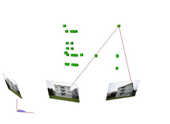
The two measurement rays from the measurements of two images are intersected in space to produce a 3D point.
A balanced forward section is calculated with the two measurement rays.
Requirements
- Oriented images of a metric camera or simultaneously calibrated images of any camera
Achievable accuracy
Very high - High - Medium - Low
Automatic detection of measurement errors
Possible by calculating the point error. However, the faulty measurement cannot be found automatically.
The measurement itself is supported by superimposing a so-called epipolar line on the images.
Potential sources of measurement errors
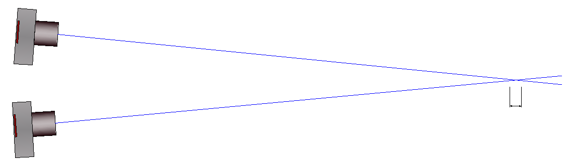
- If image viewpoints are very close to each other, this can lead to poor accuracy in the direction of view due to the slanted beam intersection:
Multi Image Measurement
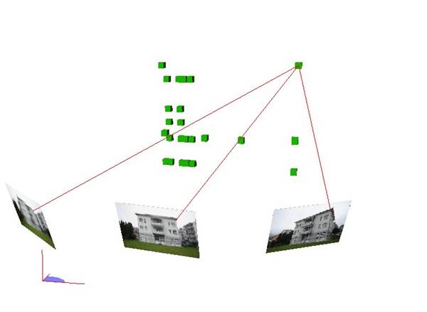
Measurement principle
All measurement rays are intersected with each other in space to produce the 3D point. The more measurements are made, the more precisely the point in space can be determined.
A balanced forward intersection is calculated with all measurement rays.
Requirements
- Oriented images of a metric camera or simultaneous calibrated images of any camera
Achievable accuracy
Very high - High - Medium - Low
Automatic detection of measurement errors
Possible by calculating the point error. Starting from 3 image measurements, the faulty measurements can be found automatically.
The measurement itself is supported by superimposing a so-called epipolar line on the images.
Potential sources of measurement errors
If image viewpoints are very close to each other, this can lead to poor accuracy in the direction of view due to the slanted beam intersection: